Choosing the right solar panel structure can determine how safely and efficiently a photovoltaic system performs over many years. Global buyers must assess more than price. Roof shape, soil conditions, wind exposure, snow load, corrosion risk, and local installation practices all influence the final decision. A coastal project may require marine-grade protection, while a farm installation may need adjustable ground supports for uneven soil.
This guide introduces ten common types of solar panel structures used in residential, commercial, industrial, and utility-scale projects. It covers rooftop rails, fixed ground mounts, adjustable frames, carport systems, pole mounts, tracking structures, and floating platforms. Each option has practical strengths and limitations. For example, a single-axis tracker can improve energy capture, but it also adds moving parts, maintenance needs, and installation complexity.
Real projects rarely match a perfect specification sheet. That matters. A structure that works well in southern Europe may need significant changes in tropical climates or regions with heavy snowfall. Buyers should verify material grades, load calculations, drainage details, fastening methods, and supplier testing records. Certifications can support confidence, but they should not replace engineering review.
Some decisions remain difficult. The lowest initial cost may create higher maintenance expenses later. Small design details, such as bolt quality or cable clearance, can affect long-term reliability. By comparing these ten solar panel structure types carefully, buyers can select a safer, more durable, and more suitable foundation for their energy goals.
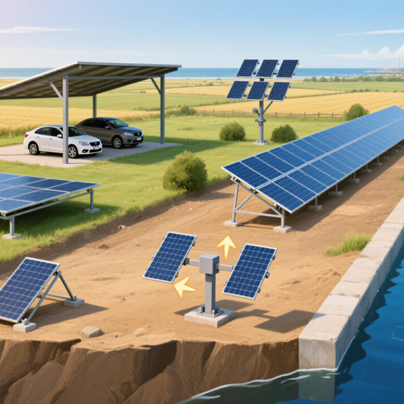
Solar panel structures are engineered frames that support photovoltaic modules above a roof or ground surface. They transfer wind, snow, and equipment loads safely into the building or foundation. More than a support, the structure controls panel alignment, tilt, spacing, and maintenance access. For global buyers, the correct design depends on climate, terrain, roof condition, and local construction requirements. Small errors matter.
Core components usually include rails, purlins, clamps, posts, beams, brackets, fasteners, and foundation connections. Rails hold the module frames in position. Clamps secure panels without damaging their edges. Posts and beams distribute loads across the roof or ground system.
Concrete footings, driven piles, or ballast may provide stability, depending on the site. Material selection also matters. Aluminum can reduce weight, while coated steel often provides higher structural strength. Coastal areas require stronger corrosion protection. Hot climates need allowance for thermal movement.
The main purpose is long-term stability with minimal shading and easy inspection. A reliable structure should maintain its geometry through seasonal weather changes. During site assessments, engineers should check roof membranes, drainage paths, soil conditions, and access routes. Not every drawing matches reality. Uneven roofs, hidden pipes, or weak foundations can change the installation plan. Buyers should request load calculations, material specifications, corrosion data, and installation tolerances. Independent technical review can reveal risks before manufacturing begins.
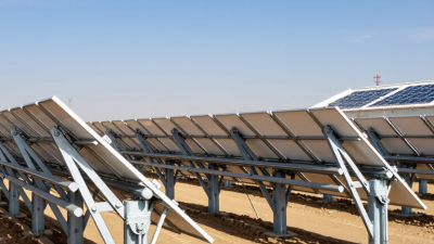
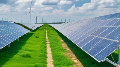
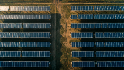
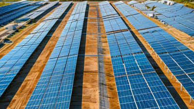
Ground-mounted solar structures support large photovoltaic arrays across open land, former industrial sites, and agricultural areas. For utility-scale installations, fixed-tilt systems remain practical where sunlight, land shape, and budget are predictable. Single-axis trackers can increase energy production, but they require moving parts, wider row spacing, and stronger maintenance planning. The best choice depends on local wind, snow, soil, and terrain conditions. Field surveys matter. A flat site may simplify piling and drainage, while sloped ground can increase grading costs and erosion risks.
Experienced project teams begin with geotechnical testing before selecting foundations. Driven piles often reduce concrete use and installation time, but refusal layers may force design changes. In corrosive soils, protective coatings and suitable materials become essential. Drainage channels should prevent standing water around posts. Rows also need enough space for maintenance vehicles, vegetation control, and safe electrical access. Small spacing errors can complicate cleaning and repairs later.
Steel and aluminum structures offer different balances of strength, weight, and cost. Hot-dip galvanizing can improve durability in demanding climates. Fasteners must resist vibration and corrosion. Engineers should verify wind uplift, snow loads, seismic forces, and tracker movement through documented calculations. No layout is perfect. A cheaper foundation may create higher repair costs years later. Cable management also deserves attention, because loose cables can rub against metal edges or collect water. Workers need clear access during installation and inspection. Safety remains essential.
| Structure Type | Typical Configuration | Typical Movement or Tilt | Common Foundation Options | Best-Suited Site Conditions | Key Advantages | Main Design Considerations |
|---|---|---|---|---|---|---|
| Fixed-Tilt Ground Mount | Module rows held at a fixed angle on steel or aluminum support frames. | Usually fixed at a project-specific tilt, often around 10°–35°. | Driven steel piles, ground screws, or concrete foundations. | Relatively level sites with predictable soil conditions. | Simple layout, few moving parts, and generally straightforward operation and maintenance. | Row spacing, wind and snow loads, pile depth, and the locally appropriate tilt must be engineered for each site. |
| Seasonally Adjustable Fixed-Tilt | Fixed-tilt frames with a small number of manual or mechanically set tilt positions. | Typically adjusted between a few preset positions; it does not track the sun continuously. | Driven piles, ground screws, or engineered concrete footings. | Sites where seasonal adjustments are practical and access for maintenance is available. | Can adapt the array angle to seasonal sun paths without a full tracking system. | Adjustment labor, locking details, safe access, and consistent settings across rows need planning. |
| Single-Axis Tracker, 1P | One module in portrait orientation is commonly mounted across each tracker row, which rotates about a horizontal axis. | Typically rotates east to west through a project-specific range, often roughly ±45° to ±60°. | Driven piles or other foundations selected from geotechnical and structural analysis. | Large sites with manageable slopes, suitable soils, and room for tracker row spacing. | Follows the sun through the day and can increase energy production compared with a fixed-tilt layout. | Requires motors, controls, row-to-row coordination, and assessment of wind, terrain, and maintenance access. |
| Single-Axis Tracker, 2P | Two modules in portrait orientation are commonly mounted across each tracker row, rotating around a horizontal axis. | Typically uses a project-specific east-to-west rotation range; limits vary by system design. | Usually driven piles, with alternatives determined by ground conditions and loads. | Broad, relatively open sites where the longer module arrangement can be accommodated. | Provides a tracker layout suited to two-portrait module mounting and utility-scale row designs. | Longer row geometry can affect structural spans, wind response, terrain tolerance, and installation logistics. |
| Dual-Axis Tracker | Support structure moves on two axes to adjust both azimuth and tilt. | Tracks the sun in two directions; movement range depends on the design. | Engineered piles or reinforced concrete foundations, subject to loads and soil conditions. | Sites where added tracking complexity is justified and sufficient space is available. | Can maintain a more direct orientation toward the sun throughout the day and across seasons. | More moving components, controls, spacing requirements, and maintenance needs than fixed-tilt systems. |
| Terrain-Following Fixed-Tilt | Fixed-tilt rows use variable post heights or adjusted supports to follow moderate changes in ground elevation. | Fixed module angle; support heights vary along the row or between posts. | Driven piles, ground screws, or engineered foundations suited to the local soil. | Sites with rolling terrain where grading is limited or undesirable. | Can reduce earthworks and help preserve existing site contours. | Survey accuracy, post-height limits, drainage, and structural tolerances must be checked carefully. |
| Steep-Slope Engineered Ground Mount | Custom fixed-tilt or tracker support designed for a sloping site, often with stepped rows or variable foundations. | Fixed tilt or a tracker range specifically verified for the terrain. | Longer driven piles, micropiles, ground screws, or rock anchors, as determined by engineering. | Sloping sites where access, geotechnical conditions, and environmental constraints permit construction. | May make use of land that is unsuitable for conventional level-row layouts. | Slope stability, erosion, access roads, drainage, construction safety, and row-to-row shading need detailed assessment. |
| Elevated High-Clearance Ground Mount | Modules are installed higher above grade than in a conventional low-clearance array. | Usually fixed tilt; the tilt and clearance are project-specific. | Long driven piles or reinforced concrete foundations designed for the elevated frame. | Sites requiring clearance for vegetation management, equipment movement, or compatible land use. | Provides greater usable space beneath the modules and can improve access below the array. | Higher frames can increase structural demands and should be checked for wind exposure, cost, and maintenance access. |
| Agrivoltaic Ground Mount | Elevated or widely spaced rows designed to allow specified agricultural activities beneath or between modules. | Usually fixed tilt, though the arrangement varies with crop, machinery, and site requirements. | Driven piles, ground screws, or other foundations selected for soil and operational needs. | Projects combining solar generation with compatible crop production or grazing. | Can support dual land use while retaining access for farm or livestock operations. | Clearance, row spacing, light levels, machinery turning space, fencing, and agricultural operations must be coordinated. |
| Ballasted Ground Mount | Low-profile frames held in place primarily by designed ballast rather than deep-driven piles. | Generally fixed tilt, with the frame angle selected for the site and system design. | Engineered concrete or other approved ballast blocks; foundation design is site-specific. | Sites where ground penetration is restricted or driven piles are unsuitable, subject to structural review. | Can avoid deep pile installation and may suit certain capped or sensitive ground areas. | Ballast weight, bearing capacity, settlement, drainage, wind uplift, and transport logistics require careful evaluation. |
| Rock-Anchored Ground Mount | Support posts or base plates are secured to competent rock using engineered anchors. | Usually fixed tilt; tracker use depends on site-specific structural and geotechnical design. | Rock anchors or drilled-and-grouted micropiles designed for the rock profile. | Rocky sites where conventional driven piles cannot achieve suitable embedment. | Offers a foundation option where shallow or hard rock limits standard pile installation. | Rock quality, anchor testing, drilling access, corrosion protection, and construction tolerances need specialist assessment. |
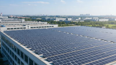
Rooftop solar mounting systems turn unused roof space into productive infrastructure. IRENA reported 1,419 GW of global solar capacity by the end of 2023. Residential and commercial rooftops are driving much of this expansion. Common structures include rail-based aluminum frames, rail-less mounts, ballasted systems, and standing-seam clamps. Each option suits different roof materials, slopes, and loading conditions.
For homes, lightweight rails can reduce roof stress and simplify installation. Tile roofs need careful flashing around attachment points. Metal roofs often use seam clamps, avoiding unnecessary drilling. Flat commercial roofs may use ballasted frames, but engineers must verify wind uplift, drainage, and structural capacity. A practical design also leaves access paths for inspection and fire safety. Small details matter.
Professional buyers should request load calculations, corrosion data, installation manuals, and evidence of testing under IEC 62548 and related safety standards. Local wind, snow, seismic, and fire requirements remain decisive. The IEA Photovoltaic Power Systems Programme has repeatedly highlighted quality assurance and system durability as essential for long-term PV performance. Yet paperwork alone is not enough. I would still inspect roof penetrations, cable routing, and clamp torque on site. One overlooked seal can create a costly leak. A perfectly designed structure can fail through poor installation, which is an uncomfortable but common lesson.
Among the top ten solar structure types, floating, carport, and agricultural systems deserve special attention.
Floating arrays use pontoons on reservoirs, irrigation ponds, or treatment lakes. Their platforms need stable buoyancy, flexible connections, and carefully designed anchors. Wind, waves, water-level changes, and ultraviolet exposure can weaken poor materials. Water changes everything. Regular inspections should check mooring lines, corrosion, cable protection, and access walkways. Field assessments often reveal that maintenance access was underestimated during planning.
Solar carports turn parking areas into productive energy sites.
Steel columns support panels above vehicles while providing shade and reducing cabin heat. Designers must coordinate clearance, drainage, lighting, vehicle movement, and emergency access. Heavy snow and strong wind require verified load calculations, not visual guesses. Carport foundations can also conflict with buried utilities. A detailed site survey prevents expensive redesigns. Space stays productive.
Agricultural solar structures require a more careful balance.
Elevated panels can protect selected crops from excessive heat, wind, or hail, but excessive shade may reduce yield. Row spacing should match tractors, harvesters, irrigation lines, and worker movement. Soil conditions also affect foundation selection. Agrivoltaic performance should be measured through crop output, moisture levels, and energy production over several seasons. Early designs are rarely perfect. Local agricultural specialists, structural engineers, and permitting authorities should review the layout together. A practical design respects both farming routines and long-term solar maintenance.
Solar panel structures range from fixed-tilt frames to single-axis and dual-axis trackers. Fixed systems have fewer moving parts and can suit sites where simplicity matters. Single-axis trackers rotate panels through the day, but need clear spacing and dependable maintenance access. Dual-axis designs follow both daily and seasonal sun paths. Their added motion can bring extra complexity. More movement is not always better.
Material choice depends on climate and site conditions. Galvanized steel offers strength, while aluminum can reduce structural weight. Coatings and fasteners need attention near coastal salt, industrial pollution, or persistent moisture. A small unprotected connection can become a weak point. I have seen specifications focus on beams while overlooking bolts. That detail deserves another look.
Buyers should check applicable structural, electrical, and corrosion requirements for the project location, rather than assume one standard fits every market. Ask for documented design loads, material grades, coating details, and installation guidance. Then compare soil reports, wind exposure, terrain, panel dimensions, transport limits, and expected service access. A tracker may improve energy yield, yet its controls and moving components affect operating costs. Fixed tilt may be easier to maintain, but can leave some site potential unused. The best choice is rarely obvious from a product sheet alone.